EMC Rectification Tips:
1、 Differential mode interference and common mode interference
Differential mode interference: It exists between the L-N lines, where current enters from L, flows through the positive terminal of the rectifier diode, then through the load, passes through the thermal ground, reaches the rectifier diode, and then returns to N. On this path, there are high-power devices with high-speed switches and diodes with extremely short reverse recovery time. The high-frequency interference generated by these devices will flow through the entire circuit and be detected by the receiver, resulting in conduction exceeding the standard.
.jpg")
Common mode interference: Common mode interference is caused by parasitic capacitance between the ground and the equipment cable. High frequency interference noise will pass through this parasitic capacitance, generating common mode current between the ground and the cable, resulting in common mode interference.
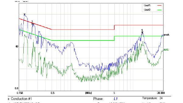
The following figure shows the conducted FALL data caused by differential mode interference. The front-end of the test data exceeds the standard, which is caused by differential mode interference:
The following figure shows the EMI principle of switch mode power supply:
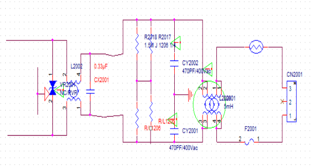
In the figure, CX2001 is a safety film capacitor (which appears as an open circuit when the capacitor is broken down or damaged). It spans between the L and N lines, and when the current between L-N flows through the load, it will bring high-frequency noise into the circuit. At this point, the function of the X capacitor is to form a circuit between the load and the X capacitor, allowing the high-frequency current to be diverted and consumed in the circuit without entering the mains power. That is, the short-circuit AC current through the capacitor prevents the interfering circuit from being connected to the outside.
Rectification measures for differential mode interference:
1. Increase the capacitance value of X capacitor
2. Increase the inductance of common mode inductance, utilize its leakage inductance, and suppress differential mode noise (because there are several winding methods for common mode inductance, such as double wire parallel winding or double wire separate winding, regardless of which winding method, due to loose winding, differences in wire length, etc., leakage phenomenon will definitely occur, that is, the magnetic field lines generated by one coil cannot completely pass through the other coil, which causes induced electromotive force between L-N lines, equivalent to connecting an inductor in series between L-N)
The following figure shows the common mode interference test FALL data:
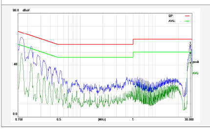
The parasitic capacitance between the power cable and the ground creates a loop for common mode interference, and the interference noise flows through this capacitance to the ground, forming a common mode interference current between the LISN cable parasitic capacitance ground, which is detected by the receiver and leads to conduction exceeding the standard (this can also explain why some motherboards pass through without grounding during conduction testing, and a ground wire exceeds the standard). In USB mode, when not grounded, the current loop can only pass through the L-diode load hot ground LED-N, and the common mode current cannot return to the LISN. The noise detected by the LISN is small, while when the cold ground of the motherboard is directly connected to the ground, there is a loop between the cable and the ground. At this time, if the common mode noise is not absorbed by the front-end LC filtering circuit, it will cause conduction exceeding the standard.)
Rectification measures for common mode interference:
1. Increase the common mode inductance
2. Adjust the LC filters on L-GND and N-GND to filter out common mode noise
3. The motherboard should be grounded as much as possible to reduce the impedance to ground, thereby reducing the parasitic capacitance between the cable and the ground.
2、 The sources of electromagnetic compatibility interference for the product include:
1. The switching circuit of the equipment switch power supply: the main frequency of the disturbance source ranges from tens of kHz to hundreds of kHz, and the high-order harmonics can extend to tens of MHz.
2. The rectification circuit of equipment DC power supply: the upper limit of the frequency of the power frequency rectification noise of the power frequency linear power supply can be extended to several hundred kHz; The upper frequency limit of high-frequency rectification noise in switching power supplies can be extended to tens of MHz.
3. Brush noise of DC motors in electric equipment: The upper limit of noise frequency can be extended to several hundred MHz.
4. The operating noise of AC motors in electric equipment: high-order harmonics can extend up to tens of MHz.
5. Disturbance emission of variable frequency speed regulation circuit: The frequency of the disturbance source in the switch speed regulation circuit ranges from tens of kHz to tens of MHz.
6. Switching noise during device operation: The upper frequency limit of noise generated by mechanical or electronic switch actions can extend to several hundred MHz.
7. Electromagnetic interference of crystal oscillators and digital circuits in intelligent control devices: The main frequency of the interference source ranges from tens of kHz to tens of MHz, and high-order harmonics can extend to hundreds of MHz.
8. Microwave leakage of microwave equipment: The main frequency of the disturbance source is GHz.
9. Electromagnetic disturbance emission of electromagnetic induction heating equipment: The main frequency of the disturbance source is several tens of kHz, and high-order harmonics can extend to several tens of MHz.
The local oscillator and its harmonics of the high-frequency tuning circuit of 10 TV electroacoustic receiving equipment: the main frequency of the disturbance source ranges from tens of MHz to hundreds of MHz, and the high-order harmonics can extend to several GHz.
11. Digital processing circuits for information technology equipment and various automatic control devices: The main frequency of the disturbance source ranges from tens of MHz to hundreds of MHz (with internal frequency doubling reaching several GHz), and high-order harmonics can extend to tens of GHz.
Reminder: (Summary of EMC's latest standards, please leave a message or email at the end of the article)
(1) YY 9706.112-2021 Medical Electrical Equipment Part 1-12: General Requirements for Basic Safety and Basic Performance Parallel Standards: Requirements for Medical Electrical Equipment and Medical Electrical Systems Expected to be Used in Emergency Medical Service Environments
(2) GB/T 38659.1-2020 Electromagnetic Compatibility Risk Assessment Part 1: Electronic and Electrical Equipment
(3) YY 9706.210-2021 Medical Electrical Equipment Part 2-10: Specific Requirements for Basic Safety and Basic Performance of Neural and Muscle Stimulators
(4) GB 9706.1-2020 Medical Electrical Equipment Part 1: General Requirements for Basic Safety and Basic Performance
(5) GB/T 17626.2-2018 "Electromagnetic Compatibility Testing and Measurement Techniques - Electrostatic Discharge Immunity Test"
(6) GB/T 17626.4-2018 "Electromagnetic compatibility testing and measurement techniques - Electrical fast transient burst immunity test"
(7) GB/T 17626.5-2019 "Electromagnetic Compatibility Testing and Measurement Techniques - Surge (Impulse) Immunity Test"
(8) GB/T 37283-2019 General Standard for Electromagnetic Compatibility of Service Robots - Immunity Requirements and Limits
(9) GB/T 38326-2019 Electromagnetic Compatibility and Immunity Test for Industrial, Scientific and Medical Robots
(10) GB/T 37284-2019 General Standard for Electromagnetic Compatibility of Service Robots - Emission Requirements and Limits
(11) GB/T 37283-2019 General Standard for Electromagnetic Compatibility of Service Robots - Immunity Requirements and Limits
(12) GB/Z 17625.13-2020 Electromagnetic Compatibility Limits Evaluation of Emission Limits for Unbalanced Facilities Connected to Medium Voltage, High Voltage, and Ultra High Voltage Power Systems
(13) GB/T 37132-2018 General Requirements and Testing Methods for Electromagnetic Compatibility of Wireless Charging Equipment
(14) GB/T 36282-2018 Electromagnetic Compatibility Requirements and Test Methods for Drive Motor Systems of Electric Vehicles
(15) GB/T 4343.2-2020 Electromagnetic Compatibility Requirements for Household Appliances, Electric Tools, and Similar Appliances Part 2: Immunity
(16) GB/T 18039.10-2018 Electromagnetic Compatibility Environment HEMP Environment Description Radiation Disturbance
(17) GB/T 38909-2020 Electromagnetic Compatibility Requirements and Test Methods for Civil Light and Small Unmanned Aerial Vehicle Systems
(18) GBT 15579.10-2020 Arc Welding Equipment Part 10: Electromagnetic Compatibility (EMC) Requirements
(19) GBT 37130-2018 Automotive Human Radiation
(20) GB/T 40134-2021 Electromagnetic Compatibility Requirements for Space Systems